O.K. We’ve learned how to get the materials together for a simple compliance measuring setup and assemble them into a working device. Now we need to calibrate the measuring weight, understand how to mechanically stabilize the top and then actually make some measurements. On another page we’ll make a compliance “map” of a successful instrument. Then we’ll think about what factors are involved in the balance between top stiffness and instrument sound.
The first thing I suggest we do is determine the effective weight that is applied to the end of the lever arm when we put our weight on the weight platform. It’s useful to do this for several reasons. First, if you ever want to compare “successful” compliance values with someone else, it’s important to understand that different weights will give different compliance values for the same top. For example, a heavier weight will give higher compliance numbers than the less heavy one for the same top. Second, if you decide to use the mathematical model for suggesting what compliance values would be useful targets for different instruments, you’ll need the effective weight for those values.
 Figure 1. Shows the lever arm with the weight on it and the scale reading in grams.
What is the effective weight? In a sense the lever arm is like a little seesaw. The closer the weight is to the pivot point, the less force is applied to the bushing. Conversely when the weight is sitting on the little weight platform near the bushing, much more force is applied to the bushing.
I use an inexpensive scale (Walmart ~$10 a few years ago) to determine the effective weight of the weight that I’ll use. The first thing to do is raise the whole scale until the suface of the measuring platform is parallel with the compliance jig lever arm. I did this just by putting an empty tofu container underneath it. High tech, yeah? With the lever arm bushing resting on the scale and NO weight on the platform, either turn on the scale or “tare” it if the scale is already on. Now put the weight on the platform and record the weight either in grams or decimal pounds. In Figure 1, the effective weight is shown to be 568 grams. It’s useful at this point to move the weight closer to the pivot point to test our earlier assertion – that it makes a difference where the weight is placed on the amount of force applied to the bushing – is correct.
At this point you can begin to compare measurements with your friends if you wish, assuming you both have measured your respective effective weights. We’ll talk about comparison calculations on another page.
Now we need to prepare the partially completed instrument body for compliance measurements. At this point the top should be attached to the sides but the back will not be so that you can adjust the height of the braces in order to get the compliance measurements you want.
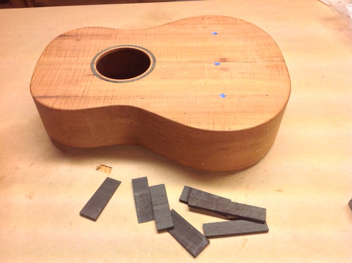 Figure 2. Partially completed body and leveling wedges.
It’s necessary to have the top as level as possible so that the underside of the bushing will lie flat on the top surface. Because the back side edges may not be a straight line from top to bottom, I make up a number of thin wedges from fretboard scrap to go along with pieces which aren’t wedges. I fill bulk space between the table top and sides with non-wedges and fine tune the leveling with the wedges. Figure 3 shows the top now ~level in one direction.
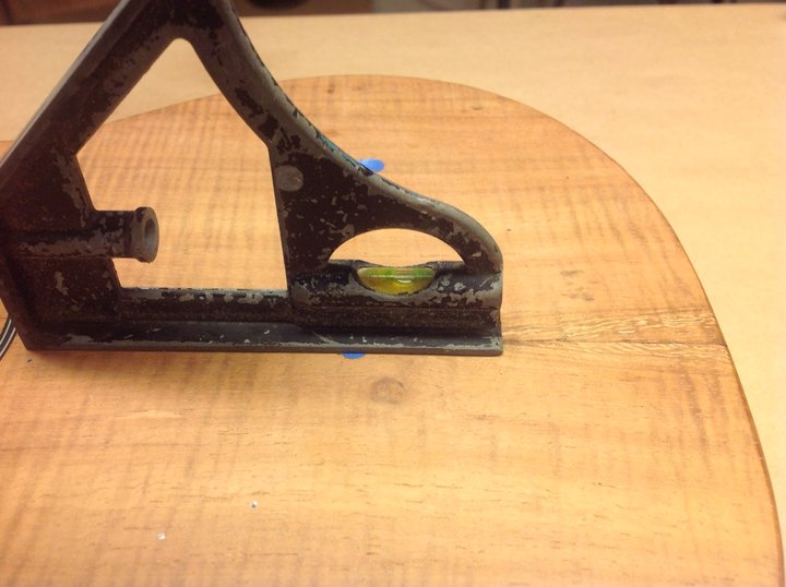 Figure 3. Spirit level ~ centered. So the top is level from top to bottom.
Repeat the process to level the top from side to side, check the first direction again and we’re good to go.
Now we trot out the base, lever arm, etc. and adjust the height of the pivot bolt so that the lever arm is parallel to the top. If it’s still not quite level, there’s some slack in the coupling that fits into the base so that upward/downward movement in the order of 1/4″ or so can happen.
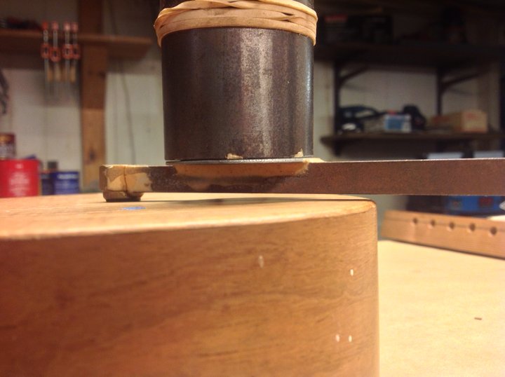 Figure 4. The lever arm is parallel to the top and ready for a compliance measurement.
Figure 4 shows the lever arm with the weight on it (somewhat prematurely). But at least the lever arm is parallel to the top. At this point we begin to choose where we want to make a measurement. Let’s just start in the middle of the lower bout for argument’s sake. First move the base, support and lever arm so that the bushing is where we want it to be. Then take the wooden dial indicator frame and dial indicator and place it such that the dial indicator stem is in the center of the bushing and the two movable pieces that support the wooden frame are near the edges of the instrument body. We put the frame support pieces on the edges so that they will have as little effect as possible on the measurement process. See Figure 5 below.
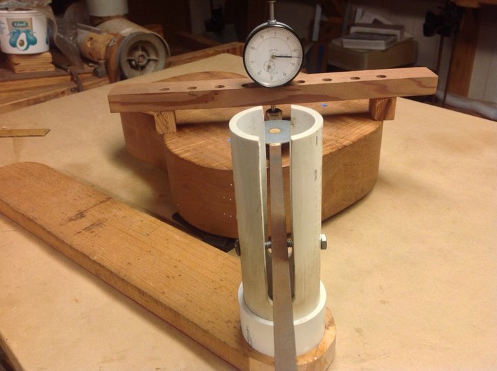 Figure 5. Shows the measurement view from the end of the lever arm.
An important point in this figure is that there is adequate spacing between the lever arm and the vertical slots in the PVC holder. The lever arm must not be encumbered in any way in its vertical movements. This is really a very simple process and jig yet some care is necessary in making the measurements to ensure a proper outcome.
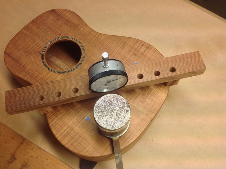 Figure 6. Top view of the measurement process with the weight in place.
Figure 6 shows the relative position of the weight and dial indicator. The weight must also not touch the wooden frame or dial indicator. This is why the frame is positioned at right angles to the lever arm.
Now let’s make a measurement.
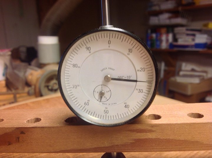 Figure 7. Reading of dial indicator before weight added.
Figure 7 shows the dial indicator initial reading. Before recording the initial measurement, it’s a good idea to lightly press on the weight platform several times to make sure that the indicator is moving freely in the bushing space and the lever arm is not encumbered. Then make the initial reading. I read approximately 25.4 on the dial in Figure 7. Remember that we will be recording DIFFERENCES between measurements with and without the weight so it’s important not to jiggle the setup. Otherwise the initial measurement will likely change and more measurements will be necessary to make certain we have continuity of measurement.
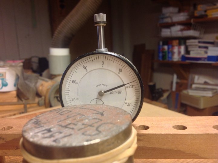 Figure 8. Dial indicator reading after weight added.
Figure 8 shows the dial indicator reading after the weight has been added. I estimate the reading to be 18.1. It’s also useful to put the weight on and off several times to make sure that the readings are consistent and the DIFFERENCES are the same each time. In this instance the difference is 25.4 – 18.1 = 7.3. The measurements are in mils or thousandths of an inch. This difference would also be 0.0073″.
Congratulations! You’ve made your first compliance measurement!
At this point you’re now wondering “Now what?”. Well, we’ll begin to talk about that in the next page where we go through the process measuring the top deflections of a “successful” instrument.