Let’s first look at an overview picture of the compliance measuring setup. Then we’ll look at the separate pieces of the apparatus and how to put them together on this page. On a separate page, we’ll look at the actual measurement process in more detail. Then we’ll take an existing “successful” instrument and make a compliance “map” of the top. On future pages (still in progress), we’ll think about what parameters are important to top stiffness and perhaps try some simple experiments.
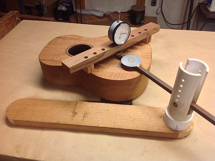 Figure 1. One incarnation of the compliance jig, ready to go.
The first picture (Figure 1) shows the basics of the process: an instrument body with the top but not the back attached to the sides; to the left a sort of lever arm thing with a little platform and ring on the end of it; and to the right a U-shaped wooden frame with holes the length of it and a dial indicator in one of the holes. Missing is the weight that sits on the platform and causes the deformation.
If you think it’s pretty simple, then I have achieved my purpose. You can build this setup in an hour or two and have the whole business cost only a little more than the cost of the dial indicator itself. Any shop has scraps from earlier projects lying about and this is mostly what I used. Let’s look at the various parts needed to put together a very simple version of the jig.
We first begin with a 1″x3″ about 15-18″ long. This is then rounded on both ends. On one end we now take a 1 1/4″ PVC coupling and trace the outside perimeter near one end of the base.
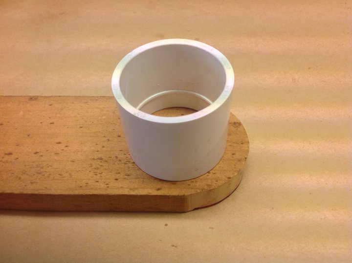 Figure 2. The coupling, poised at one end of the base, ready for perimeter tracing.
The trace is made and a jig saw used to cut the hole for the coupling. I glue and clamp the entrance cut to the hole, then adjust the inside of the hole with a Dremel sander head. The coupling fit should be a little loose for easy turning but not wobbly.
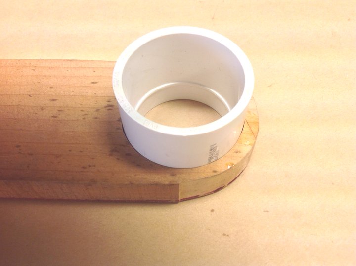 Figure 3. Coupling resting in rotation hole.
Next we need to make the PVC holder for the lever arm. The holder has a pair of slots that are wider than the lever arm (~1/2″ across) and a series of holes at right angles to the slots. The holes will hold a bolt which is the pivot point for the lever arm. Since the lever arm is 3/8″ square rod, the bolt should probably be 1/8″ and the holes in the PVC the same.
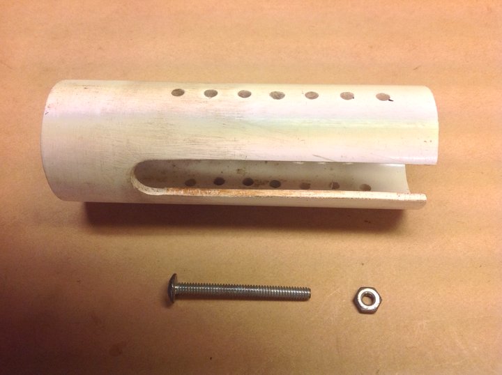 Figure 4. The lever arm holder with associated bolt and nut.
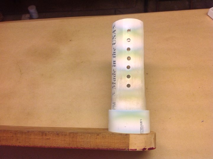 Figure 5. Lever arm base, along with PVC coupling and lever arm holder, now all in place.
The lever arm is made of 3/8″ square iron/steel or aluminum rod about 15 ” long, available from the local hardware store. A 9/32″ hole is drilled in the side ~1/4″ away from the center of balance. A 2″ diameter fender washer is epoxied near one end on the top of the rod with the center of the washer 1 3/4″ from the end of the rod. A hexagonal bronze bushing whose inner diameter is large enough to comfortably accommodate the tip of a dial indicator is epoxied or brazed to the end of the rod.
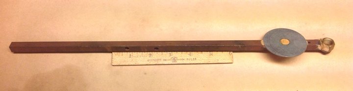 Figure 6. The lever arm with associated weight platform and dial indicator stem guide.
Brazing or silver soldering the bushing would be better than epoxy because the latter is a little more fragile than the former. Yes, the bushing has broken off several times, but super glue has revivified it sufficiently to allow me to “press on”.
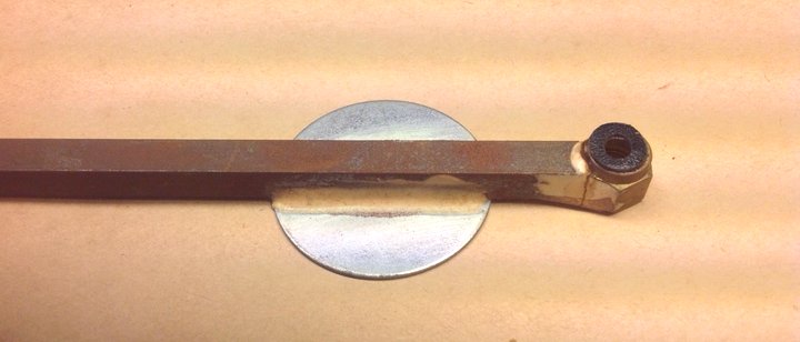 Figure 7. This shows the underside of the business end of the lever arm.
Put some cork, leather or neoprene on the underside of the bushing to pad that surface and not damage the top, especially if you are measuring compliances on finished instruments.
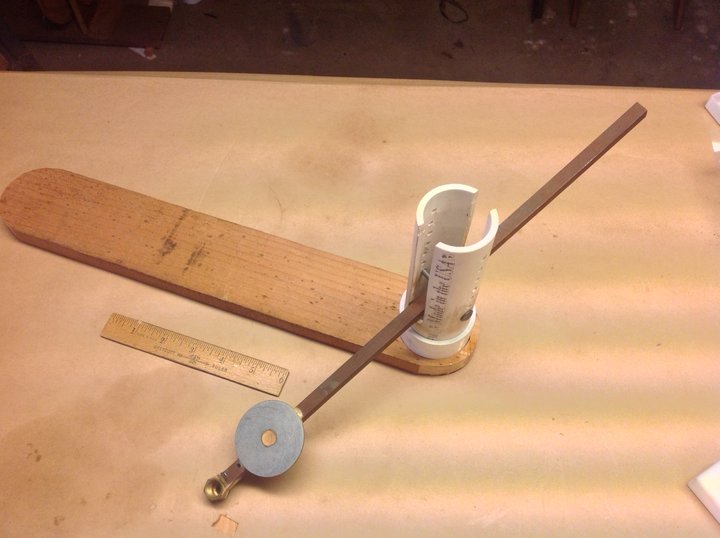 Figure 8. This figure shows the assembled lever arm, holder and base.
The wooden frame (Figure 9) that the Dial Indicator sits in is a piece of 1″x 2″ x12″ with pairs of holes drilled about 1 1/2″ apart. The user can change the length and hole spacing to suit him/herself for the instrument being studied. The size of the holes is such that the outer stem of the Dial Indicator fits snugly but is still easy to remove – often it’s 3/8″ in diameter. It’s also useful to have the holes asymmetrically placed on the frame so that by simply reversing the frame, the indicator is in a different location. There are a pair of wooden pieces that the frame rests on. These in turn will rest on the edges of the instrument.The top and bottom of these pieces should be flat and parallel to one another. The length of the frame is such that each end extends somewhat beyond the edge of the instrument during use.
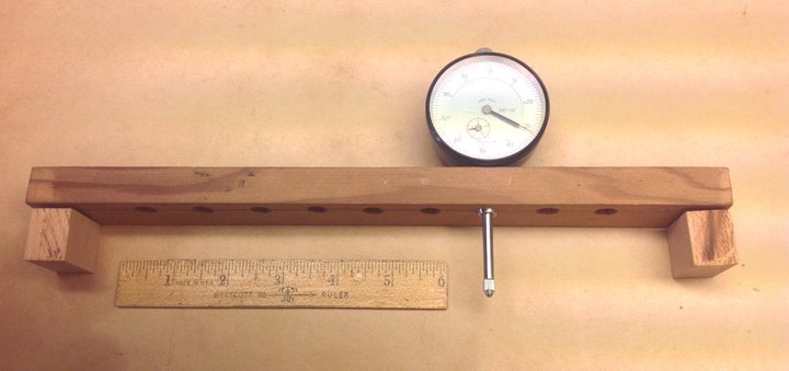 Figure 9. The wooden frame showing hole distributions and the dial indicator in place.
The indicator I use costs $15 from Harbor Freight. Typically, the total deformation is 0.003-0.005″ for a weight weighing about 1 1/2 lbs. Some folks use a heavier weight (nearer 3lbs) so that the deflections are larger.
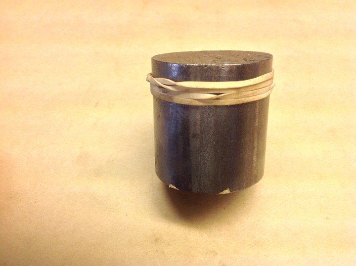 Figure 10. The ~1.5lb steel/iron weight that I use in making my measurements.
The weight used is a piece of ca. 2″ diameter by 2″ long steel rod, weighing about 1.5 lbs. It’s not critical to have a weight of this exact size – a little heavier will still be fine. Although this weight is sufficient for ukuleles and classical guitars for my purposes , some folks are using a somewhat heavier weight for their measurements. The rubber bands on the weight make it easier to pick up and put down on the platform. Note that the outer edge of the weight coincides with the outer edge of the fender washer. It’s very important to put the weight at the same place on the washer each time a measurement is made.
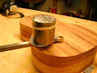 Figure 6: View of weight on stem washer.
Since I eventually wanted to have a sense of the actual force corresponding to a particular deformation, I measured the “weight” of the lever arm with the weight on the platform using an accurate postal scale. With the weight in place, the downward force of the lever arm on the brass bushing for my setup is ~1.3 lbs. This calibration operation will be discussed in more detail in the next page. Again, it’s not necessary to have this exact value – something close will be fine.