Routing the Soundhole and Soundhole Trim Channel
Routing the Soundhole and Soundhole Trim Channel is actually a fairly straightforward procedure once you have the jig made. This “making the jig” thing is such a truism for lutherie that there was once a joke in American Lutherie about it: Question: “How many luthiers does it take to change a light bulb?” Answer: “Only one, but he has to build a jig first.” As in several other instances, this jig was loosely patterned after several designs from the early Data Sheets from the Guild of American Luthiers, now recompiled and improved in their first book publication, “Lutherie Tools”. This jig is not particularly flexible like the one sold by Stewart McDonald. One of the jigs described here is required for each size instrument or application, but it does its job extremely well and without any adjustments or fiddling around, something which is a plus for me.
Once again, I wish to stress safety. You can use a router or laminate trimmer to do the cutting here, but at 25-30,000 RPM things can go badly very quickly. Routers are dangerous and all precautions listed by the manufacturer must be observed in order to “have a nice day”. Don’t use this when tired, under medication which causes drowsiness, etc. The author writes this article as a community service, but assumes no legal responsibility for the final functionality of this jig.
Jig…top view 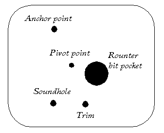 – The first drawing shows a plan view of the jig. Plexiglas ~ 1/4-3/8″ thick works well for this application. Most of mine are about 6″x9″ with the corners rounded. There are four different sets of holes in this jig:
The Pivot Point — this hole represents the center of the circle that the router bit will trace. Through this hole will go a 1/4″ bolt stem which will connect the jig to the plywood work board upon which the soundboard rests.
The Anchor point — there are usually three points of attachment to connect the router frame to its plastic base. We will be using only two of these three points although it is the reader’s option to use the third hole as well. The Anchor Point is the screw attachment of the jig to the router frame which acts as another center of rotation. More on this later.
The Trim Channel and Soundhole Points — these holes will alternate as the second attachment point of the jig to the router frame. The Trim Channel Point positions the jig to cut a larger radius than the Soundhole Point. The positions of the two points are meant to be relative to one another in the drawing and not to actual scale.
The Router Bit Pocket — this is the hole in the jig that the router bit will protrude through in order to cut the soundhole trim channel and the soundhole itself.
Jig…side view
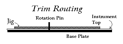
The second drawing shows a side view of the jig, soundboard and backing plate. The router is not shown attached to the jig at this time for simplicity sake (and because I couldn’t face trying to draw a router). Also not shown are three clamps for attaching the soundboard to the backing plate. The backing plate is a piece of 3/4″ plywood that’s several inches larger than the soundboard in both length and width. The rotation pin that’s sticking up is a 1/4″ hex head bolt that has a smooth shaft. This means that the original bolt was somewhat longer and had threads; the threaded portion was removed and the cut end nicely rounded. A Forstner bit or a brad point bit was used to make a shallow, concentric hole on the underside of the backing plate larger than 1/4″ pilot hole but clearly smaller than the hex head. When this is done, the hex head can be tapped into both the rotation pin hole and shallow hole and the rotation pin will be held in place by friction fit of the hex head in the shallow hole.
Making the Jig: In the centerline of the long axis of the jig, drill the 1/4″ diameter Pivot Point hole about 1/3 of the way from one end of the jig. With the router unplugged, upside down and a bit in the collet with the end of the bit below the level of the router frame, place the jig on the router frame. Position the jig so that two of the threaded attachment holes in the router base are equally spaced from the long axis centerline and slightly away from the Pivot Point hole. See photograph below for actual jig. Mark the position of the upper one of the holes, which we now label the Anchor Point.
With a brad point or Forstner drill bit, drill a hole slightly greater than the diameter of the head of one of the machine screws to a depth also slightly greater than the depth of the head of the screw. Now drill a second smaller hole in the center for the shaft of the machine screw. When done, the screw should drop easily into the hole with enough protruding out the other side of the jig to make firm contact with the router base threads and also not be sticking up above the surface of the jig which will be next to the soundboard. Attach the jig to the router with the machine screw so that it will still rotate easily around the Anchor Point.
The router bit should be just below the under surface of the jig. Now rotate the jig back and forth on the router frame and mark the travel path of the router bit with a magic marker or Pentel pen. Observe how the distance of the router bit travel path varies from the Pivot Point . This is the crux of the working of the jig, because this varying distance can be translated into a varying cutting radius.
You must now decide where to drill the Soundhole and Trim Channel Point holes. Let’s choose the Soundhole Point first. The distance from the outer edge of the router bit to the center of the Pivot Point will be the radius of whatever soundhole we cut. Rotate the jig until that distance equals the radius of the soundhole for your instrument. Mark where the router bit tip is on the travel path. Now also mark where the second machine screw hole in the router base frame is. This latter position will be the location of the Soundhole Point. Rotate the jig again, now searching for the radius of your trim channel. Keep in mind that you may use a different router bit for the trim channel than for cutting the soundhole and make your radius adjustments accordingly. Again mark the place on the travel path where the router bit is and where the Trim Channel Point machine screw hole should be.
As before for the Anchor Point, drill concentric holes for the machine screw that will fit into either the Soundhole or Trim Channel Points. Then using a 1/2-3/4″ Forstner bit, drill out the Router Bit Pocket on the travel path between the two marked points on the travel path so that soundboard chips will easily be able to escape the cutting area. Probably centering the bit on each of the two marked points followed by cleaning out the intervening area is a good approach.
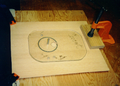
The first photograph shows the jig alone resting on an instrument top with the rotation pin sticking up through the Pivot Point. The Router Bit Pocket is to the right of the pin, the Anchor Point above it and the Trim Channel and Soundhole Points below. Actually, careful observation will show that the jig is upside down since the machine screw head pockets are on the upper surface; in actual practice this surface would be against the soundboard. The soundboard is resting on the base plate and is held in place by three clamps and (until the soundhole has been cut out) the rotation pin.
View of rounter in place
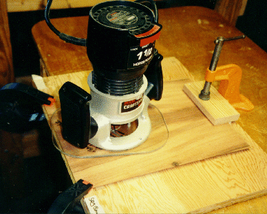
The second photograph shows the router in place on the jig. Note that the rotation pin is visible through the router frame and the router bit is at the top of the soundboard.
Order of Operations for Cutting the Trim Channel:
The soundboard template is positioned over the correctly thicknessed soundboard and the center of the soundhole is marked at an appropriate place on the centerline seam. A 1/4″ diameter hole is drilled on the mark to match the diameter of the rotation pin. For softwoods, I recommend a lacquer wash coat before cutting the trim channel in order to reduce the possibility of tear out.
The soundboard is gently placed onto the rotation pin and backing plate, being careful to apply pressure at the top and bottom of the soundboard rather than the sides. Rotating the soundboard often helps in both the insertion and removal procedures. Pressure at the top and bottom of the soundboard will be less likely to open the center seam than pressure on the sides. I know, I know, if the seam is glued properly it’s stronger than the wood around it, but this logic also holds for the likelihood of breaking along the grain of the softwood top as compared with across the grain. Clamp the top and bottom of the soundboard to the backing plate. At this point, the face of the jig which will be against the soundboard is checked for little toodies which may be stuck to it and could scar the surface of the soundboard. These may be removed by gently scraping the surface with a safety razor. Check also to see that the two screws holding the jig to the router are not sticking up above the surface of the jig. For best results cutting the channel you should be using a left-hand spiral, down cutting router bit.
The router/jig are lowered onto the rotation pin with the router bit at the top of the soundboard. The reason for this is that if something goes wrong at this point, mistakes will be covered by the end of the fretboard. A 360 degree cut is made and then another in the reverse direction. I do this because the trim I’m using seems to be slightly non-standard and the second cut makes things fit better. Your trim may only require one cut. Practice on scrap…
The router/jig is removed, debris dusted away and the soundboard taken off the base plate, again being careful to use the top and bottom of the soundboard as holding points rather than the sides.
Order of Operations for Cutting the Soundhole: 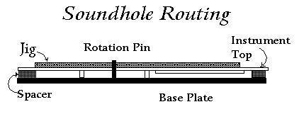
I cut out the soundhole after the braces and soundhole backing plate are glued on but not shaped to final dimensions. This means that the top and bottom of the soundboard no longer have the backing plate immediately against the surface and that spacers are needed to bridge the gap, as shown in the third drawing. I put two spacers of 1/4-3/8″(thick)x1″(wide)x12-14″(long) of wood which elevate the soundboard above the base plate the thickness of the braces. These spacers are placed at the upper and lower edges of the top directly beneath the clamps and are shown in drawing number three. The top is again placed onto the rotation pin and clamped. Jig…side view
The router needs to make a 360 degree cut to create the soundhole, but when this happens, the center disk can now spin wildly causing the router bit to chatter and nibble nervously at the formerly pristine soundhole edge. This irksome process can be avoided by temporarily stopping the router travel a few degrees shy of the 360 needed, turning off the router, and while the bit is still spinning but slowing down rotate the final few degrees. The inertia of the router is still easily sufficient to cut the remaining material but not to drive the disk to distraction.
If you enjoy the technical side of things, please consider buying my book “Left-brain Lutherie” . Although no longer sold by StewMac, you can buy directly from me.
I enjoy writing these pages and hope that they are interesting and useful to the reader. I’ve stopped building at this time and still need to generate some income in order to continue to expand this website with more useful articles. If this page was helpful to you and you would like to make a $10.00 donation in order to have more pages like it, please use the donation button below. Thank you.
