Thoughts on the Mechanical Properties of Braces–Part I. Cross-sectional Shape & Composites
If you enjoy the technical side of things, please consider buying my book “Left-brain Lutherie” . Although no longer sold by StewMac, you can buy directly from me.
After I looked at a number of guitar building books in the sections dealing with bracing the top and back of the instrument, I began wondering what the effect of various bracing cross-sections might have on the stiffness in the finished instrument. Some braces are triangular, others rounded and others simply rectangular. Along their length, braces can be more or less the same height or tapered in various ways. Newer bracing systems include composite materials (usually a sandwich of wood/graphite carbon epoxy/wood ).
In order to sort out some of the geometries, let’s first look at the effect of cross-sectional shape on brace stiffness. Please note that the author is trying to present a simplified view of the problems. For additional details on terminology and calculations, the reader is referred to such standard texts as: Applied Strength of Materials, Jensen & Chenowith, McGraw-Hill, New York, 1975; Mechanics of Materials, Gere & Timoshenko, PWS, Boston, 1997; Mechanics of Materials, Hibbeler, Prentice Hall, Upper Saddle River, N.J., 1997.
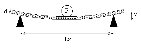
In the page dealing with measuring wood properties , we studied the static deformation of a beam of wood using the equation
Ex = ( K*P*Lx3) / ( y*Ly*d3 ) (1)
where
Ex = Young’s modulus, parallel to grain, N/m2
K = a constant; for center-loaded beams = 0.25
P = force applied to plate/beam in kg
Lx = distance between fixed supports parallel to grain, meters
y = deflection (s) of plate/beam, meters
Ly = length of plate/beam perpendicular to Lx, meters
d = thickness of plate/beam, meters
Those using the lbi system of units can convert the Young’s modulus in N/m2 to psia by dividing by 6895.
Static Deflection Cross-Section
If we now rearrange the equation to solve for deformation, y, rather than Young’s Modulus along the grain, Ex ,
y = ( K*P*Lx3) / ( Ex*Ly*d3 ) (2)
Engineers prefer to look at a more general form of this equation:
y = ( P*Lx3) / ( 48*Ex*I ) (3)
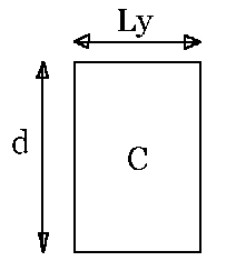
where I represents the Moment of Inertia of the beam cross-section and the constant K has been subdivided. In the case of a rectangular beam whose centroid coincides with the center of the beam, the moment of inertia, I, is:
I, rectangle = (Ly*d3)/(12) (4)
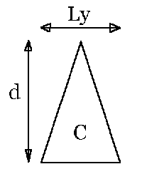
and we can see that the constant K from equation (1) is still the same. For a beam of triangular cross-section, the moment of inertia, I, is:
I, triangle = (Ly*d3)/(36) (5)
So in comparison with a rectangular brace of the same width and height, a triangular cross-section brace would need to be either three times as wide or ~ 1.44 times as high to obtain the same stiffness. Note that 1.44… is the cube root of 3.
If you now have the same stiffness for both cross-sections, what have you gained or lost in terms of the triangular brace being heavier or lighter than the rectangular one? Since both cases use the same material, the weight per unit volume of brace is constant. The cross-sectional area of the rectangle is simply Ly*d, while that of the triangle is 1/2*Ly*d. If we make the base of the triangle 3 times wider than the rectangle to achieve equivalent stiffness, then the area of the triangle is 3*1/2*Ly*d, or larger than the rectangle by 50%. If we make the height of the triangle 1.44 times taller to achieve equivalent stiffness, then the area of the triangle is 1.44*1/2*Ly*d or 0.72*Ly*d. So it’s clearly more effective from a weight standpoint to make the triangular brace taller rather than wider to achieve the same stiffness. Making the triangle taller rather than wider achieves a reduction in the braces’ weight by ~28% while achieving the same stiffness as the rectangle. Now the builder needs to make a personal choice about whether it’s more difficult and/or important to make slightly taller, proportionately lighter triangular braces or stick with rectangular ones.
It has recently become popular to make composite braces using sheets of graphite carbon epoxy material sandwiched between one’s brace wood of choice. If you are making brace composites, a simple way to think about how the composite enhances the wood sandwich is to transform the composite into an equivalent single material. First, we define n, the ratio of the Young’s Modulus of the more stiff material E1 to the less stiff material E2 :
n = E1 / E2 (6)
n is now factored times the thickness of the stiffer material to obtain an equivalent thickness in terms of the less stiff material. The sum of the thickness’ of the original less stiff material and the size transformed more stiff material is now the new equivalent width of the brace.
For example, let’s consider the case of a square Douglas fir brace 1/2″ wide and 1/2″ high, and say that you’d like to double the stiffness. If you cut the wood in half, making two 1/4″ wide pieces and glue in a 0.10″ graphite carbon epoxy layer, then you have the wood/graphite carbon/wood sandwich. Since the Young’s modulus of the graphite is about 5 times more than the wood, then it is as though you had a 1″ wide piece of the original wood ( 1/4″ + 1/4″ + 5*0.1″ = 1″). Since stiffness is directly proportional to width, you’ve doubled the stiffness of the brace by adding a piece of graphite carbon epoxy of these dimensions and properties.
Graphite carbon is really rough on tools and the dust is worse than wood dust in terms of health problems, or so I’ve been led to believe. So is it worth it to put in the graphite carbon epoxy layer? Let’s look at the example above. By putting in the 0.1″ thick layer, you’ve made the new composite brace stiffer by effectively increasing the width of the brace by a factor of 1.0/0.5 = 2.0 (the new effective width divided by the old width without the insert); so the new brace is twice as strong. But you could get the same thing by increasing the height of the brace by a factor of 1.26, wherein 1.26 ~the cube root of 2, since stiffness is proportional to the cube of height. That is, if the brace were 0.50″ high initially, then making it 1.26*0.50 = 0.63″ would yield the same stiffness as adding the graphite carbon epoxy strip (without the health hazards…).
But is the wood/graphite sandwich better from a weight standpoint? Graphite carbon epoxy composite has a specific gravity of ~ 0.9. Let’s say that we use Douglas fir for the wood portion and that it has a specific gravity of 0.45. Cross-sectional area times specific gravity will give us a sense of the weight per unit cross-section. Let’s also assume an initial brace height of 0.50″ as in the example above. So, the cross-sectional weight of the wood/epoxy sandwich is:
2*.25*.5*.45 + .1*.5*.9 = 0.16 (7)
whereas the cross-sectional weight of the Douglas fir with an increase in height from 0.5 to 0.63 is:
.5*.63*.45 = 0.14 (8)
or slightly less than the composite. I would encourage the reader to do the math for their own set of materials to determine whether the extra effort involved in making the wood/graphite carbon epoxy sandwich is worth it for their own particular situation.
Does this mean that we shouldn’t use graphite carbon epoxy for stiffening other portions of an instrument? I suggest that in situations which are dimensionally constrained, such as a neck of fixed width, that this material is very useful. Further, I like to use it for bridge patches on all sizes of my ukuleles because of its low profile and resistance to creep. In both of these cases (a neck insert and a bridge patch), there is minimal working of the material and thus greater safety for the builder.
I enjoy writing these pages and hope that they are interesting and useful to the reader. I’ve stopped building at this time and still need to generate some income in order to continue to expand this website with more useful articles. If this page was helpful to you and you would like to make a $10.00 donation in order to have more pages like it, please use the donation button below. Thank you.


