Joining the neck to the body
In American Lutherie #15 / Fall 1988, there is an article by R. E. Brune “The ‘Belly Art’ of Japanese Lutherie” (pp. 46-55) wherein a brief mention is made of how the heel face of the neck is mated to the body.
To quote: “The guitar body was mounted onto the holder and the neck into a movable jig. The sanding belt moves between them with the grit toward the neck. The jig holds the neck in the proper alignment along the center line of the body and also accounts for the slight upward angle of the neck. The jig is brought up to contact the moving belt. In this way, each individual neck and body were perfectly mated, as the body became the sanding form for each individual neck.”
The following assembly description has two parts: 1) shows how I use a simplified form of this device to prepare the heel faces of my ukulele necks for joining to the body using simple plywood alignment boards and a 2″ wide sanding belt in my band saw; 2) shows how a modified version of the plywood alignment board is then used for neck to body gluing. Please note that a 14″ band saw is large enough to handle all four sizes of ukuleles, but too small for guitars.
The Jig 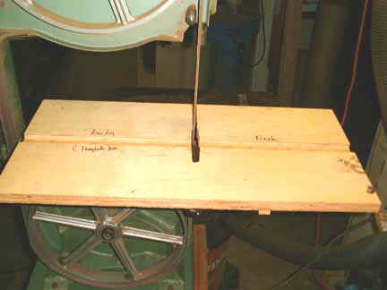
The first device to be constructed will be the band saw sanding belt alignment jig. Use good quality, 3/4″-1″ plywood for the jig and store it flat to avoid any possibility of warping. As can be seen in the first figure, the board has a 1″ wide x 3/8″ deep slot that runs the long axis of the board. Board dimensions are about 2 feet long and 1 foot wide for a 14″ band saw. A keyhole is cut into the board perpendicular to the slot to allow the sanding belt to gain access to the center of the board. The hole is widened to ~ 1/2″ in the slot area. The distance of the slot from the left end of the board is controlled by the size of the band saw; for a 14″ band saw a distance of 11″ is about right. The underside of the board now needs to have a wooden guide installed which will fit into the slot on the band saw table. The guide should be fairly close fitting but still allow for easy movement along the slot. The idea here is that the alignment board will not be continuously moved forward and backward during the sanding process, but it should be fairly easy to have it be in the right place when the sanding begins.
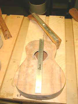 We need to think of a way to align the body and neck so as to have them properly oriented when we do the sanding and gluing operations. I use aluminum bars ( 12″ long, 1″ wide and 1/4″ thick ) which are double-stick taped to the centerline of the body and of the neck as shown in Figure 2 to the right of this text. These bars should slide easily but with no wobble in the alignment board slots. I tried both wood and Plexiglas bars early on, but settled on aluminum because of its uniform dimensions and ease of use. A vertical line scribed or cut into the end faces of each bar will make positioning the bar on the neck and body centerlines easier.
I make the sanding belts myself, although I’m sure that they could be ordered from anywhere that sells sanding belts. I use 120 grit, cloth backed, 2″ wide sanding tape and allow about a 1″ overlap, cut at about a 45 degree angle. Contact cement works well for me. This is the stuff that you glue Formica down with. The fumes from this stuff are hazardous, so please do the gluing outside.
At one point, I feathered the edges but ultimately decided that it didn’t seem to make much difference, as long as you don’t mind a rhythmic clacking sound as the tape joint passes the heel face. You will have to play with the belt tension and probably adjust the top wheel angle as well to make the belt track correctly.
The Sanding Process 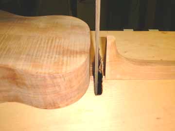 Figure 3, showing the body and neck ready for sanding O.K., let’s try one. I usually scribe a line on the surface of the neck which will mate to the fretboard at the 12th or 14th fret positions, depending on how long a neck the instrument will have. About 1/8″ of the heel extends beyond that line, to allow for curvature of the sides of the body where it will mate to the neck face. It’s always nice if the angle of the side to the top where the neck will join is 90 degrees but somehow mine never are. Fortunately, this approach is very forgiving. Using double stick tape, we attach one aluminum bar to the centerline of the body and the other aluminum bar to the centerline of the neck. In each case, the end of the bar should be about 3/8″ from the edge of the body or the scribe mark on the neck. Don’t want to sand the bar, right? Make sure to vacuum and cloth wipe the surface of both the neck and top of the body before taping so that the tape will adhere properly. Figure 3, shown above and to the left now shows the body and neck positioned on the jig with the sanding belt between them and with the grit side facing the neck face.
Before going further, let’s make sure that the body is properly aligned for lateral movement. What does that mean? If the surface of the top of the instrument is slightly curved, then the instrument has the capability of a variety of alignments. Undesirable. Depending on the amount of top curvature, I put one or more layers of masking tape on both sides of the upper bout to keep it from rocking laterally during the sanding and gluing process. How many to put? First, see if any lateral movement occurs. A little? Put 1-2 layers. Lots? Begin with 3 layers and continue until there is still very slight movement. We don’t want to actually raise the top surface away from the neck surface plane.
It’s also important that the surface of the side be as flat as possible vertically. By this I mean that a straightedge placed on the heel block center seam will show no spaces at the top-to-side or back-to-side edges. That is, those areas haven’t become rounded during the process of sanding the sides. When viewing the instrument from the front or back, this area can be rounded, just not from the side.
What about dust? I tape the hose from the vacuum system to within about 1-2″ of the sanding belt. This is most easily done with two lines of masking tape, one on the outer right edge of the band saw table and one about an inch from the edge of the circular center hole where the tape is. Another piece on the left edge of the table will keep the jig flat. Turn on the band saw.
I put the sanding tape in the band saw so the outer edge of the sanding tape is above the joint. I also keep both sanding shields off the band saw which means that the wheels are open, spinning and slightly scary. Be careful here. You will surely have to adjust the upper wheel angle so that the belt will track properly. How much to tension the belt? Make it fairly firm and turn on the machine. If the belt flies off, the tension was too low, right? Make it a little tighter.
It is important to remember that you really don’t want to use the sanding belt to remove most of the wood if you can help it. If you do, it will overheat the heel face and perhaps even loosen the glue joints on the heel. I use a belt sander with a 120 grit belt to remove most of what needs to go. Go slowly when using either the belt sander or the sanding belt in the band saw. It’s better on your nerves and you’ll make far less ruinous mistakes on the neck.
 Let’s start with the band saw. Figure 4, example of neck to body joint Turn it on. Adjust the body so that it’s pressing slightly against the belt. Bring the neck close to the body and move the jig so that a little of the belt is sticking out on either side of the neck. If you don’t have the neck centered, there will be grooves in the heel face. Not good. Press the heel lightly but firmly against the body then pull the neck back and turn off the band saw. There will be a smooth section on the heel face caused by the sanding belt. Pull the jig toward you a little and press the neck against the body without the belt in between. You’ll now have a sense of how much needs to be removed by the belt sander. Go to the belt sander and take some off using the end of the belt sander. Go back to the band saw and check again where the smooth areas are. Continue to cycle back and forth until you have removed heel face material up to the scribe line and the whole face is smooth as well. The joint should look like the Figure 5,
  near the top of this paragraph. If you tried to remove too much at once with the band saw sanding belt, the surface of the heel face may be hot and not smooth at the joints. I cool the heel face by placing against the palm of my hand, then lightly but firmly, doing another 3-4 seconds of band saw belt sanding. This will usually result in a clean, smooth face now ready for the gluing process.
The Gluing Process This is another time when we want to slow down and look carefully at what we’ve done thus far. In principle, the centerline of the neck and the centerline of the body have been aligned with one another and a nice heel face surface has resulted using the band saw sanding belt. Now look at the center of the heel and the centerline of the back. Uh, oh. The centerline of the back may not be in the center of the heel. This can happen because the centerline of the back and front don’t exactly align with the centerline of the side join at the heel block or because the angle of the centerline at the heel block is not 90 degrees. Whatever. I usually make my heel cap widths somewhat larger than the final size so that I can trim them down to make the back centerline in the centerline of the heel. So remove a little from one side or another if necessary and sand the heel shape as nicely as possible toward the finished shape.
Another, simpler jig is now necessary. Copy the first jig but put no keyhole or tracking bar underneath. In the center where the keyhole would be, rout out a pocket two inches along the groove and three inches across the groove to the depth of the groove. This will give a little slack for the epoxy to escape to if necessary. Cut a piece of wax paper about 4 inches wide and 3 inches across. This will fit in the groove under the aluminum bars and prevent the epoxy from sticking to the jig. The neck to body joint should be in the center of the wax paper. 
Put the body and the neck on the jig and press them together along the track. The fit should be the same as in the band saw jig. Draw a line on the body along the sides of the neck. Remove the body and make three marks along the centerline of the side to side join at the heel block. In a minute we’ll drill holes where these marks are, tap small brads in and use the brads for preventing the heel face from moving laterally during the gluing process. The marks should be two on one side of the line (top and bottom) and one on the other side of the line (middle). Drill the holes about 1/8″ deep. Tap the brads in lightly but firmly. Cut off most of the brad so that only a little more than 1/16″ sticks up from the surface. Sharpen the tip of each brad with a fine file, being careful not to damage the surface of the sides outside of the pencil lines.
 Bring the body back to the gluing jig and bring the heel in contact with the brads on the body firmly enough to make marks on the heel face. Enlarge the marks with an awl and drill them to a depth of ~ 1/8″. Enlarge them again with the awl and check the neck and body for fit. I then put a strip of archival tape (very thin and easily removable) along the pencil line with about 1/16″ overlap. This allows much easier cleanup after the resin has firmed up.
I use epoxy to join the neck and body. Figure 8 shows a number of necks spring clamped to a vertical surface so that the heel face will be horizontal. 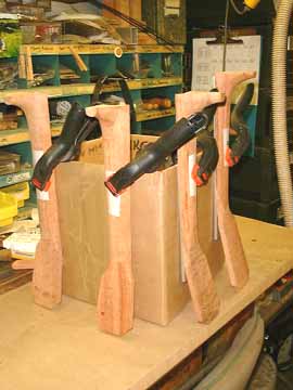 I use an epoxy which takes several hours to harden with the result that it penetrates the pores of the wood very well. There have been instances of its going nearly 1 1/2″ into the end grain! The take home message here is to allow enough time for the resin to penetrate the end grain of the heel face so that the glue joint won’t be starved during the clamping process. I usually allow about 10-15 minutes for resin penetration before clamping. I use about 5 grams of resin for each neck, which is a lot, but it’s much easier to not use leftover resin than to rush around and mix more in the middle of everything. Near the end of the gluing process, I mix very fine koa dust with the remaining epoxy and butter it on the joint so that there will be some squeeze out.
In the meantime, the bodies have been clamped to the gluing jig using large rubber bands. It is important during this part and subsequent clamping and gluing operations that as little lateral force is used as possible. 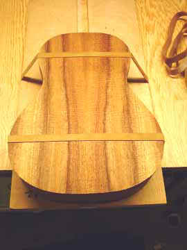 By this I mean that we don’t want to alter the position of the aluminum bars on the neck and body center lines, a possibility which can easily occur.
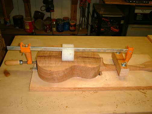
As a result of several suggestions from readers (and my own diminished capacity as a jig builder) the neck is now clamped in place with a “Pony” sliding clamp as shown below.
The wooden block on the right side of the clamp is held in place by tightened wing nuts on two 1/4-20 threaded rods that are screwed into brass inserts in the plywood. A piece of neoprene or cork under the shaped surface of the block prevents damage to the neck. Another piece of the same material beneath the left hand side of the clamp serves the same purpose. The white hard foam block in the center keeps the clamp from damaging the back of the instrument.
When you’ve buttered up the joint, place the neck onto the alignment slot and firmly screw on the wooden clamping block. Then firmly press the heel face against the body side with the alignment brads. Resin putty should ooze out all around the joint. Now put on the clamp and apply firm but not excessive pressure. Clamping should be firm but not too forceful. You only want to maintain the squeeze out of the resin. You should also check the alignment of the body aluminum bar at this point to make sure that it hasn’t slipped.
I don’t remove the resin at this time, because it’s still possible for the joint to take a little more resin. If you’ve cleaned all the resin away at this stage, then a little later you may see a little crack at the joint where more resin was sucked in. The trick here is to wait 1 1/2 to 3 hours for the resin to become cheese-like in consistency, at which point it can easily be removed with chisel and single-edged razor blade. When removing the aluminum bars from the neck and body, use a lateral twisting motion rather than an upward one and they will come off more easily. I usually store the glued up assembly overnight on a flat surface before the next step of gluing on the fretboard.
If you enjoy the technical side of things, please consider buying my book “Left-brain Lutherie” . Although no longer sold by StewMac, you can buy directly from me.
I enjoy writing these pages and hope that they are interesting and useful to the reader. I’m slowing down in my building at this time and still need to generate some income in order to continue to expand this website with more useful articles. If this page was helpful to you and you would like to make a $5.00 donation in order to have more pages like it, please use the donation button below. Thank you.