Static Measurement of Young’s Modulus Parallel to Grain (Ex)
If you enjoy the technical side of things, please consider buying my book “Left-brain Lutherie” . Although no longer sold by StewMac, you can buy directly from me.
Many and many are the ways of measuring the Young’s moduli or elasticity coefficients of wood. Herein I show a simple framework reminiscent of those used by Brian Burns, Charles Woods and probably many others during the last 100 years who had access to a dial micrometer and calibrated weights.
Figure 1. View of Frame without Sample 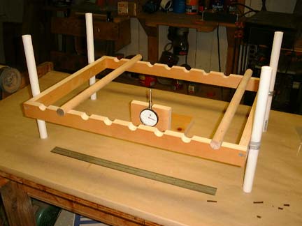
Figure 2. Frame with Sample & Weight 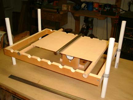
Figure 1 shows a simple frame made of 1″x2″ fir. It is 22″ long and 16.5″ wide, but individuals should adjust the dimensions to fit their own needs. An 18″ ruler is on the table for scale. The notches are 1″ in diameter and 1″ dowels rest in them. The notches are 2.5″ apart. It’s probably easiest to use a 1″ diameter Forstner bit to drill all the holes down the center line of a 1″x4″ and then cut the board lengthwise down the center in order to make sure that the notches line up correctly. Figure 2 shows the measuring frame with a sample plate in place and a rod of known weight depressing the plate.
It’s important that the frame be level front to back and left to right. The four 1″ diameter PVC “legs” are held in place with galvanized pipe clips and short drywall or sheet metal screws for ease of friction adjustment. The frame height should be adjusted so that the tip of the micrometer is about 10% of its travel range above the upper surface of the dowel. This means that the tip will be pushed down somewhat when a sample plate is placed on the dowels at the beginning of the measurement process.
Figure 3. Micrometer Base – Front View 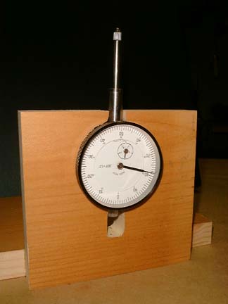
Figure 4. Micrometer Base – Back View 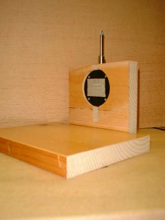
Figures 3 and 4 show a simple right angle wooden frame holds the micrometer by friction. The base is a little large to keep the instrument steady. The size of the circular hole in the upright is obtained by tracing the outline of the back of the instrument. Note that there are channels above and below the circular cutout to allow the stem to both fit in the frame and travel when displaced.
Figure 5. Calibrated Weights for Plate Deformation 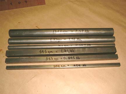
Figure 5 shows six calibrated weights I use in the deflection measurements. All the rods are 12″ long. The cylindrical rods are 1″ (1212 gm; 2.67 lbs), 3/4″ (685 gm; 1.51 lbs) and 1/2″ (301 gm; 0.664 lbs) in diameter. The rectangular rods are 5/8″ (595 gm; 1.31 lbs), 1/2″ (383 gm; 0.845 lbs) and 3/8″ (208 gm; 0.459 lbs) square. I use the cylindrical rods for plates and the rectangular rods for braces.
When making a measurement, please make sure that the micrometer tip is centered both between the rods and the sides (resting on the centerline). I usually make several deflection observations with each weight and use all three different weights at each different rod-to-rod distance for a better average.
Let’s review the equation for determining Young’s modulus once more. We are calculating Ex, Young’s modulus parallel to grain, so the wood grain is perpendicular to the dowels in their respective slots as shown in Figure 2. If we use several different sized weights we’ll obtain a better average value of the stiffness modulus. These calculations are also discussed in “Understanding Wood”, Bruce Hoadley, Taunton Press, pp. 124-126. The appropriate equation is:
Ex = ( K*P*Lx3) / ( y*Ly*d3 )
where
Ex = Young’s modulus, parallel to grain, psia
K = a constant; for center-loaded beams = 0.25
P = force applied to plate/beam in lbs
Lx = distance between fixed supports parallel to grain, inches
y = deflection (s) of plate/beam, inches
Ly = width of plate/beam perpendicular to Lx, inches
d = thickness of plate/beam, inches
Those using the mks system of units can convert the Young’s modulus in psia to N/m2 by multiplying by 6895.
Static Deflection Cross-Section
Figure 5. Schematic Showing Variables 
O.K., let’s try a set of sample measurements. Please refer to the spreadsheet PlateExStatCalc.xls for this example.
PlateExStatCalc (to download double-click or option-click)
In the calculation example we have a plate of Western red cedar which is 15.82 inches long , 11.2 inches wide (Ly) and 0.106 inches thick (d). We can set the rods apart from one another at the following distances (Lx): 17.5″, 15.0″, 12.5″, 10.0″ and 7.5″. We have three different cylindrical rods which weigh: 2.67, 1.51 and 0.664 lbs. What is Young’s modulus in psia for this piece?
Using the above equation:
Ex = ( K*P*Lx3) / ( y*Ly*d3 )
The spreadsheet calculates MOE (modulus of elasticity, Ex) estimates corresponding to as many distances and weights as the user wishes to use. Please note that if user actual weights and distances are different than those in the spreadsheet, corresponding calculation changes must be made.
As we look in the spreadsheet at the first few estimates for the rod-to-rod distances of 15″ and 12.5″, the MOE estimates are within a few percent of one another. For shorter distances, successively lower estimates occur. Figure 6 below shows this effect for several different wood species. I’ve plotted an average of the highest MOE estimates divided by each individual estimate on the vertical axis, versus the ratio of the rod-to-rod length (Lx) divided by the plate width (Ly) on the horizontal axis. Clearly, there is a problem with accurate estimation of Ex below an Lx/Ly ratio of about 1.3. I’m currently looking into equations which will take additional wood measurements into account to explain this behavior. It’s also clear that turning the board 90 degrees and trying to estimate Ey by deflection won’t work because the same effect will obtain.
Figure 6. Effect of Lx/Ly on the Measured Value of Ex 
In summary, we can accurately estimate Ex for instrument plates by a simple deflection method for Lx/Ly values greater than 1.3. Estimates of Ey must wait for another approach.