Estimating the Stiffness of Ukulele and Guitar Necks
I have finished writing my book “Left-Brain Lutherie: Using Physics and Engineering Concepts for Building Guitar Family Instruments: An Introductory Guide to Their Practical Application”. Details can be found here.
I’m sure that we’ve all looked at older instruments of different types, noticed that the neck was warped in varying ways and wondered whether it was possible to prevent such excessive curvature. Surely there must be a way of calculating how stiff a neck needs to be in order to reduce the amount of warping to an acceptable minimum. Well, there is. In fact the mathematics necessary to do the calculations have been in place for probably 200 years and the actual stiffness physical property data for at least a 100 years.
Where to look? Interestingly enough, because of my love for old books (“If you want to find out something new, read an old book”) I first found the necessary equations and technical explanations in a 1916 edition of the Mechanical Engineers Handbook, Lionel S. Marks, ed., McGraw-Hill, New York. A more modern text with considerably more examples and explanations could be Jensen and Chenowith’s “Applied Strength of Materials”, McGraw-Hill, New York. I recommend the latter, which might be found in your nearby University library or available through inter-library loan.
I made an initial stab at a spreadsheet program which came pretty close to the correct answers, but my friend Josh Gordis, an Assoc. Professor of Mechanical Engineering at the Naval Postgraduate School in Monterey, did the heavy sledding to make more accurate estimates of EI, the product of Young’s modulus, E, and the moment of Inertia, I. He can be reached at the address at the bottom of the page for more detailed questioning of his math and such. The new spreadsheet uses my earlier basic outline at the beginning and end, and his mathematics in the middle.
The spreadsheet is divided into three general sections: 1) Materials engineering and dimensional data; 2) Calculation of the neutral axis (ybar) and then the value of EI for the composite neck; 3) Calculating the geometry of the low string-to-neck angle and then the deformation of the neck as seen by the change in action at the 12th fret.
The neck under consideration is a composite assembly of three components: 1) the neck itself, usually made of wood, and comprising largest proportional volume of the composite; 2) the fretboard, usually made of a wood different from the neck wood for reasons of durability or looks; 3) the insert, generally made of material many times stiffer than either the neck or fretboard, and smallest in proportional volume. as shown in the first figure:
Neck Cross-Section
Note that each material has a modulus or material property associated with it: En is the stiffness modulus in psi for the neck; Ef for the fretboard; and Et for the truss rod.
The analytical model assumes an elliptical cross-section for the neck itself. The symbols are defined below both in the figure and a separate listing:
Symbols for calculations defined
All of the following variables, along with the Young’s moduli above, must be entered into the spreadsheet before the final neck deflection can be calculated; it is, however, possible to obtain neck deflections in the absence of the truss rod and/or fretboard.
Neck 1/2 Width, W; This is the width of the neck immediately below the fretboard. Because the neck cross-section has bilateral symmetry, Josh can use equations which describe one half or the other of the cross-section to obtain the proper result. On the spreadsheet, the actual width is entered and the half-width calculated and used in the equations for the user.
Neck Depth, R; this is the distance from the underneath side of the fretboard to the outside of the neck.
Fretboard 1/2 Width is the same as the neck width.
Fretboard Thickness, tf; the average thickness of the fretboard.
Truss Rod 1/2 Width, m; once more, like the neck width, the actual width of the truss insert is entered into the spreadsheet and the 1/2 width calculated and used in the proper equations.
Truss Rod Depth, n; the depth of the truss rod.
Neck Length, L; although not shown on the figure, the neck length must also be entered into the spreadsheet early on along with the other data. We define neck length as the distance from the nut to the body of the instrument.
String Tension, P; the total pull of the strings in pounds.
String Action; the distance between the strings and the fret at the neck/body join.
The first equation to bring together the varying geometries and properties of the components is the calculation of the neutral axis of the cross-section. If a beam is bent by placing a weight in the center, the neutral axis is that point in the cross-section, above which the material is in compression and below which the material is in tension.
The location of the neutral axis (ybar) is given by:
Neutral Axis Equation
![]()
The next equation uses the value of ybar and earlier data for the calculation of EI for a given composite.
EI for Composite Neck
![]()
We can now calculate the deflection of an end-loaded beam (our instrument neck) using the equation:
90 degree defl = (P * L3) / (3 * E * I)
In this equation the tension of the strings P is assumed to be at right angles to the neck. Needless to say this would be near the ultimate case of the string action being too high, but it does give an initial deflection number. To approximate the pull of the strings at their more normal angle, the spreadsheet then calculates the sin of the small angle formed by the surface of the fretboard and the strings in their normal position, using the string length (nut to body) divided into the action (fret to string distance at the neck-body join).
sin (string-fretboard angle) = L / (String Action)
This small number is then multiplied times the 90 degree deflection to obtain a more realistic actual deflection. The resulting number is the change in action at the neck to body join. Smaller deflection numbers relative to the neck-only example mean that the neck is stiffer.
Deflection at neck/body join = sin (string-fretboard angle) * 90 degree deflection
The following Microsoft Excel spreadsheet which performs the above calculations is offered as a downloadable file.
wk1neck (Microsoft Excel file) (to download double-click or option-click)
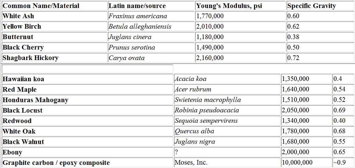
Since most folks won’t have Young’s moduli at their fingertips, the following table is offered for convenience. The woods listed are those mentioned in the newsgroups rec.music.makers.guitar.acoustic and rec.music.makers.builders. More can and will be added as time permits. These are average values for these materials and meant only to be used as a starting point when using the spreadsheet. Unless otherwise noted, the wood data are for materials which are at ~12% moisture content, quartersawn and air dried. Sources of such information include “Wood Handbook: Wood as an Engineering Material” USDA Forest Products Laboratory, Agriculture Handbook # 72, (1974) stock # 0100-03200; and “Understanding Wood”, R. Bruce Hoadley, (1980) Taunton Press, Newtown, CT ISBN 0-918804-05-1.
We understand that not everyone is facile with spreadsheets but may still have an active interest in the extent to which graphite carbon/epoxy composite truss rods affect neck stiffness, as well as the effects of neck thickness and fretboard thickness and composition. With that in mind we will present case studies for different sized instruments.
Example 1: Classical guitar — Input information- neck width, 2.0″ (W=1.0); neck depth, 0.75″; neck length, 13.0″; wood type, Honduras Mahogany; fretboard depth, 0.25″; fretboard wood, Ebony; truss rod width and depth, 0.50″ (m=0.25); truss rod material, graphite carbon/epoxy composite; action at 12th fret, 0.13″.
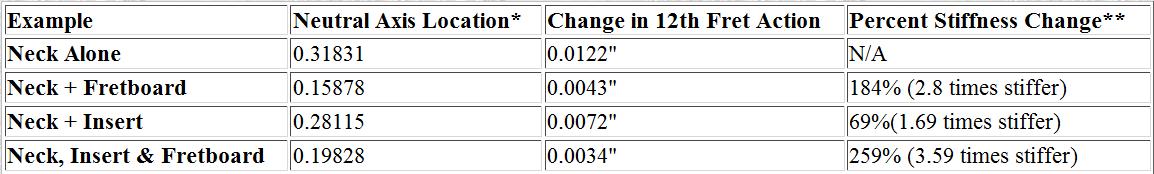
* Neutral axis position is measured from neck-fretboard interface; positive values towards neck. **Percent changes calculated relative to neck stiffness without insert or fretboard.
In this case, the addition of the fretboard has a considerably greater effect than the truss rod. What is not obvious in this calculation is the amount of long-term cold flow or “creep”. Eventual wood movement may be 3-5 times that of the initial deformation, while the truss rod may suffer little or no movement. The true function of the truss rod in this situation may be that of promoting greater neck stability rather than immediate stiffness.
Example 2: 8-String Kawika Tenor Ukulele — Input information- neck width, 1.5″ (W=.75); neck depth, 0.5″; neck length, 8.5″; wood type, Hawaiian koa; fretboard depth, 0.1875″; fretboard wood, ebony; truss rod width and depth, 0.375″ (m=0.1875); truss rod material, graphite carbon/epoxy composite; action at 12th fret, 0.11″.
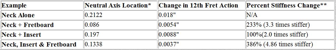
Example Neutral Axis Location* Change in 12th Fret Action Percent Stiffness Change**
* Neutral axis position is measured from neck-fretboard interface; positive values towards neck. **Percent changes calculated relative to neck stiffness without insert or fretboard.
In this case, the addition of the truss rod has a greater effect on stiffness and will surely also be more important in terms of long-term stability. Having the spreadsheet also allows us to understand why many ukulele makers who don’t concern themselves with the mechanical aspects of neck stiffness can have severe problems with neck deformation.
In the shop at the moment I have an ukulele with an obviously bowed neck made by a well-known local manufacturer. The instrument has no truss rod, the fretboard is koa rather than ebony, the neck shape is flattened and is ~7/16″ thick while the fretboard is ~3/16, and there are 14 frets between nut and body making the neck length 9.25″. Using the same 95# pull, the neck-only deformation at the body for this ukulele is 0.032″ (compared with 0.0120 above for our neck only case) and the neck + fretboard deformation is 0.010 (compared with 0.0054 above for our neck + fretboard case). So there is 2-3 times the deformation expected for this instrument compared with ours: (1), not including longer term creep of the wood which occurred because of the absence of a truss rod; and (2), not even comparing our case where we include the truss rod.
More case studies will be presented as time allows.
For questions and comments:
Joshua H. Gordis
Naval Postgraduate School
Dept. of Mechanical Engineering Code ME/Go
Monterey, CA 93943-5146
Internet: gordis@me.nps.navy.mil
I enjoy writing these pages and hope that they are interesting and useful to the reader. I’ve stopped building at this time and still need to generate some income in order to continue to expand this website with more useful articles. If this page was helpful to you and you would like to make a $5.00 donation in order to have more pages like it, please use the donation button below. Thank you.