Thoughts on the Mechanical Properties of Braces–Part II. Effects of Bracing on Top Stiffness
If you enjoy the technical side of things, please consider buying my book “Left-brain Lutherie” . Although no longer sold by StewMac, you can buy directly from me.
In the first part of our study of braces we looked at the effect of cross-sectional shape on brace stiffness. In this section we’ll do simple calculations regarding the effects of various cross-sectional bracing shapes on top stiffness. Once more please note that the author is trying to present a simplified view of the problems. For additional details on terminology and calculations, the reader is referred to such standard texts as: Applied Strength of Materials, Jensen & Chenowith, McGraw-Hill, New York, 1975; Mechanics of Materials, Gere & Timoshenko, PWS, Boston, 1997; Mechanics of Materials, Hibbeler, Prentice Hall, Upper Saddle River, N.J., 1997. The first section from Part I is repeated for reader convenience.
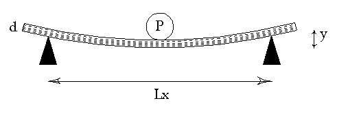
In the page dealing with measuring wood properties , we studied the static deformation of a beam of wood using the equation
Ex = ( K*P*Lx3) / ( y*Ly*d3 ) (1)
where
Ex = Young’s modulus, parallel to grain, psia
K = a constant; for center-loaded beams = 0.25
P = force applied to plate/beam in lbs
Lx = distance between fixed supports parallel to grain, inches
y = deflection (s) of plate/beam, inches
Ly = length of plate/beam perpendicular to Lx, inches
d = thickness of plate/beam, inches
Those using the lbi system of units can convert the Young’s modulus in psia to N/m2 by multiplying by 6895.
Static Deflection Cross-Section
Figure 1. Side view of center loaded beam deflection
If we now rearrange the equation to solve for deformation, y, rather than Young’s Modulus along the grain, Ex ,
y = ( K*P*Lx3) / ( Ex*Ly*d3 ) (2)
Engineers prefer to look at a more general form of this equation:
y = ( P*Lx3) / ( 48*Ex*I ) (3)
where I represents the moment of inertia of the beam cross-section and the constant K has been subdivided.
Rather than just use the simple brace shape, we will now look at the situation of a brace glued to the top. This combination of simple shapes is called a composite shape. Figure 2 below shows a section of the top as viewed from the heel or tail block with a single rectangular brace glued to the underside. The thickness of the top is exaggerated for the convenience of labeling the various dimensions.
Figure 2. First case – Rectangular Brace glued to unit width of top
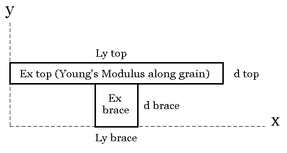
The same general approach toward calculating engineering properties of a composite shape still applies: first we must determine the centroid or center of balance of the shape, y-bar, and then the moment of inertia, I for each of the areas and then for the composite shape. Jensen and Chenowith, pp. 118-119, show an example of such calculations for this composite shape. I have created a spreadsheet which allows the reader to enter the four variables in Figure 2 (Ly top, d top, Ly brace, d brace,) in order to calculate y-bar and I for this composite shape.
It often happens (at least to me) that the Young’s modulus of the brace material is different from the Young’s modulus along the grain of the top. The variables Ex top and Ex brace are used to normalize the dimensions of the brace material so that a single value of Ex can be used in the calculations. This type of calculation was presented in Part I, in the section dealing with the graphite composite insert into a brace.
In the spreadsheet, the reader can also input the length of the top strip, Lx, and the load to be applied to the center, P, in order to determine what amount of deformation, y, the strip will undergo. I have additionally included what deformation the same load would make for the brace alone and for the top strip alone. Finally, I have estimated to what thickness the top would need to be increased if it were to have the same amount of deformation that the top and brace had together. This is done by having an increment table (first column) from which values are added to the top thickness and the absolute difference in deflection between the incrementally thickened top and the composite top+brace are posted (second column). Those thickened top values which have deflection differences less than 0.005″ are then posted in the third column.
The name of the spreadsheet for the brace / top model in Figure 2 is RECteedeflcalc.xls and is an Excel spreadsheet.
RECteedeflcalc (to download double-click or option-click)
Readers will not be surprised to find that analogously to Part I, I have included spreadsheets for both triangular and elliptical cross-section braces as well.
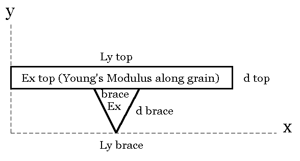
Figure 3. Second case – Triangular Brace glued to a unit width of top
The name of the spreadsheet for the brace / top model in Figure 3 is TRIteedeflcalc.xls and is an Excel spreadsheet.
TRIteedeflcalc (to download double-click or option-click)
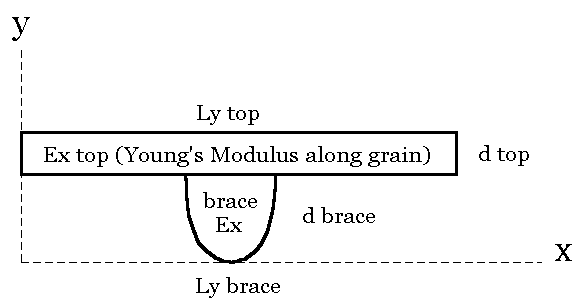
Figure 4. Third case – Ellipsoidal Brace glued to a unit width of top
The name of the spreadsheet for the brace / top model in Figure 4 is ELLIPteedeflcalc.xls and is an Excel spreadsheet.
ELLIPteedeflcalc (to download double-click or option-click)
Constructive criticism is always appreciated with respect to these models…
I enjoy writing these pages and hope that they are interesting and useful to the reader. I’ve stopped building at this time and still need to generate some income in order to continue to expand this website with more useful articles. If this page was helpful to you and you would like to make a $5.00 donation in order to have more pages like it, please use the donation button below. Thank you.